Kubernetes Configuration (Kubeadm HA Cluster)
Step-by-step guide to deploying a highly available Kubernetes cluster on-prem using kubeadm. Covers CoreDNS setup, external etcd with SRV discovery, HAProxy + KeepAlived API load balancing, and Calico networking (iptables → eBPF). Includes configs, verification, and best-practice automation tips.

Pre-requisites
Before deploying the cluster, make sure to meet the following requirements:
- High Availability Requirements: A highly available cluster relies on consensus algorithms (like Raft) for data consistency to prevent data loss when nodes fail. This means you need at least 3 physical hosts and at least 3 etcd instances and 3 control plane instances. While the Kubernetes kubelet itself is lightweight, running all the core components, scheduling components, observability stack, CNI plugins, etc., will increase resource usage. Each machine should have at least 8 CPU cores and 16 GB of RAM. For the full recommended setup, use 3 machines with 32 cores and 128 GB RAM each. Always use an odd number of nodes to achieve optimal quorum in leader elections.
- Network Connectivity: Kubernetes networking is quite complex. To ensure network reliability and high availability, use a plain host network (no special configurations or restrictions) so that we can freely adjust network topology and settings. All machines in the cluster must have full network connectivity to each other.
- External Load Balancer & NAT: In a fully private, on-premises environment, you won’t have cloud-managed load balancers or NAT gateways. We recommend using external hardware (such as F5, FortiGate, or similar) to provide these capabilities:
- Expose the Ingress Controller to the internet with load balancing.
- Expose the API Server to the internet with load balancing.
- Provide internal load balancing for the API Server within the cluster.
- Act as a NAT gateway (egress) for the cluster, allowing containers/hosts to access the public internet.
- Administrative Access: You must have administrator privileges on all machines and be able to SSH into all hosts/VMs.
Plan
Our plan is to set up 16 VMs across 4 physical hosts to form a basic highly available Kubernetes cluster. (Note: Topics like choosing a Kubernetes dashboard, designing a backup strategy, setting up monitoring, etc., are outside the scope of this article.)
Cluster layout:
|
Component |
No. |
IP |
Hostname |
vCPU |
RAM |
Storage |
|---|---|---|---|---|---|---|
|
Etcd |
1 |
10.30.0.11 |
etcd-1 |
4 |
8 GB |
20 GB (Local) |
|
Etcd |
2 |
10.30.0.12 |
etcd-2 |
4 |
8 GB |
20 GB (Local) |
|
Etcd |
3 |
10.30.0.13 |
etcd-3 |
4 |
8 GB |
20 GB (Local) |
|
Etcd |
4 |
10.30.0.14 |
etcd-4 |
4 |
8 GB |
20 GB (Local) |
|
Control Plane |
1 |
10.30.0.21 |
master-1 |
8 |
16 GB |
60 GB |
|
Control Plane |
2 |
10.30.0.22 |
master-2 |
8 |
16 GB |
60 GB |
|
Control Plane |
3 |
10.30.0.23 |
master-3 |
8 |
16 GB |
60 GB |
|
Control Plane |
4 |
10.30.0.24 |
master-4 |
8 |
16 GB |
60 GB |
|
Worker |
1 |
10.30.0.31 |
worker-1 |
8 |
32 GB |
80 GB |
|
Worker |
2 |
10.30.0.32 |
worker-2 |
8 |
32 GB |
80 GB |
|
Worker |
3 |
10.30.0.33 |
worker-3 |
8 |
32 GB |
80 GB |
|
Worker |
4 |
10.30.0.34 |
worker-4 |
8 |
32 GB |
80 GB |
|
Worker |
5 |
10.30.0.35 |
worker-5 |
8 |
32 GB |
80 GB |
|
Worker |
6 |
10.30.0.36 |
worker-6 |
8 |
32 GB |
80 GB |
|
Worker |
7 |
10.30.0.37 |
worker-7 |
8 |
32 GB |
80 GB |
|
Worker |
8 |
10.30.0.38 |
worker-8 |
8 |
32 GB |
80 GB |
|
Load Balancer |
1 |
10.30.0.41 |
lb-1 |
4 |
8 GB |
20 GB |
|
Load Balancer |
2 |
10.30.0.42 |
lb-2 |
4 |
8 GB |
20 GB |
|
DNS |
1 |
10.30.0.51 |
dns-1 |
4 |
8 GB |
20 GB |
|
DNS |
2 |
10.30.0.52 |
dns-2 |
4 |
8 GB |
20 GB |
Additional Virtual IPs:
10.30.0.100 – 10.30.0.110– reserved for Kubernetes Service LoadBalancer (VIPs for Service objects).10.30.0.20– internal virtual IP for the Kubernetes API Server (used by the control plane load balancer).
Note: Although Proxmox VE (PVE) supports Ceph as a storage backend, for the etcd VMs we force the use of local disk and recommend using a high-performance SSD for best etcd performance.
CoreDNS on VM Layer
Given our architecture lacks an internal cloud DNS or load balancer for service discovery (and etcd uses TLS for peer discovery), we will set up an internal DNS service using CoreDNS. This internal DNS will:
- Resolve the Kubernetes API server’s name to multiple A records (for the four control plane nodes in a round-robin fashion).
- Resolve each node’s hostname to its IP address (for ease of internal communication).
- Provide DNS SRV records for etcd discovery (for the TLS-enabled etcd cluster).
We will deploy CoreDNS on two dedicated nodes (DNS-1 and DNS-2 with IPs 10.30.0.51 and 10.30.0.52, respectively) for high availability.
Install CoreDNS
First, install CoreDNS on the two DNS nodes:
# Create a system user for CoreDNS and necessary directories
sudo useradd --system --no-create-home --shell /usr/sbin/nologin coredns
sudo mkdir -p /etc/coredns/zones

# Download and install CoreDNS (choose an appropriate version)
VER=1.13.1
curl -LO https://github.com/coredns/coredns/releases/download/v${VER}/coredns_${VER}_linux_amd64.tgz
tar xzf coredns_${VER}_linux_amd64.tgz
sudo install -m0755 coredns /usr/local/bin/coredns
Note: By default, Ubuntu’s systemd-resolved service listens on127.0.0.53:53for DNS. We will not disable this stub listener; instead, in the CoreDNS configuration we will bind CoreDNS to its own IP (10.30.0.51or10.30.0.52) to avoid port conflicts.
Zone File
On both DNS-1 and DNS-2, create the zone file /etc/coredns/zones/db.k8s.internal. (Whenever you update this file in the future, make sure to update it on both DNS servers to keep them in sync.)
Use an SOA serial number (e.g., 2025110205 below) and increment it with each update:
$TTL 300
@   IN SOA ns1.k8s.internal. admin.k8s.internal. (2025110205 3600 600 604800 300)
    IN NS   ns1.k8s.internal.
    IN NS   ns2.k8s.internal.

; NS glue records for the name servers
ns1 IN A   10.30.0.51
ns2 IN A   10.30.0.52

; --- Kubernetes API (VIP) ---
api         IN A     10.30.0.20
apiserver   IN CNAME api.k8s.internal.
kubernetes  IN CNAME api.k8s.internal.

; --- etcd hosts ---
etcd-1  IN A  10.30.0.11
etcd-2  IN A  10.30.0.12
etcd-3  IN A  10.30.0.13
etcd-4  IN A  10.30.0.14

; --- Control Plane (Masters) ---
master-1  IN A  10.30.0.21
master-2  IN A  10.30.0.22
master-3  IN A  10.30.0.23
master-4  IN A  10.30.0.24

; --- Workers ---
worker-1  IN A  10.30.0.31
worker-2  IN A  10.30.0.32
worker-3  IN A  10.30.0.33
worker-4  IN A  10.30.0.34
worker-5  IN A  10.30.0.35
worker-6  IN A  10.30.0.36
worker-7  IN A  10.30.0.37
worker-8  IN A  10.30.0.38

; --- Load Balancers ---
lb-1  IN A  10.30.0.41
lb-2  IN A  10.30.0.42

; --- DNS servers ---
dns-1 IN A  10.30.0.51
dns-2 IN A  10.30.0.52

; ============================================================
; SRV records for kube-apiserver (control plane API endpoints)
; ============================================================
_apiserver._tcp      10  IN  SRV   10  50  6443  master-1.k8s.internal.
_apiserver._tcp      10  IN  SRV   10  50  6443  master-2.k8s.internal.
_apiserver._tcp      10  IN  SRV   10  50  6443  master-3.k8s.internal.
_apiserver._tcp      10  IN  SRV   10  50  6443  master-4.k8s.internal.

; ==============================
; etcd DNS SRV discovery (TLS)
; ==============================
_etcd-client-ssl._tcp.etcd.k8s.internal. 300 IN SRV 0 0 2379 etcd-1.k8s.internal.
_etcd-client-ssl._tcp.etcd.k8s.internal. 300 IN SRV 0 0 2379 etcd-2.k8s.internal.
_etcd-client-ssl._tcp.etcd.k8s.internal. 300 IN SRV 0 0 2379 etcd-3.k8s.internal.
_etcd-client-ssl._tcp.etcd.k8s.internal. 300 IN SRV 0 0 2379 etcd-4.k8s.internal.

_etcd-server-ssl._tcp.etcd.k8s.internal. 300 IN SRV 0 0 2380 etcd-1.k8s.internal.
_etcd-server-ssl._tcp.etcd.k8s.internal. 300 IN SRV 0 0 2380 etcd-2.k8s.internal.
_etcd-server-ssl._tcp.etcd.k8s.internal. 300 IN SRV 0 0 2380 etcd-3.k8s.internal.
_etcd-server-ssl._tcp.etcd.k8s.internal. 300 IN SRV 0 0 2380 etcd-4.k8s.internal.

; Non-TLS version (if needed, uncomment and use http:// in etcd configuration)
; _etcd-client._tcp.etcd.k8s.internal. 300 IN SRV 0 0 2379 etcd-1.k8s.internal.
; _etcd-client._tcp.etcd.k8s.internal. 300 IN SRV 0 0 2379 etcd-2.k8s.internal.
; _etcd-client._tcp.etcd.k8s.internal. 300 IN SRV 0 0 2379 etcd-3.k8s.internal.
; _etcd-client._tcp.etcd.k8s.internal. 300 IN SRV 0 0 2379 etcd-4.k8s.internal.
; _etcd-server._tcp.etcd.k8s.internal. 300 IN SRV 0 0 2380 etcd-1.k8s.internal.
; _etcd-server._tcp.etcd.k8s.internal. 300 IN SRV 0 0 2380 etcd-2.k8s.internal.
; _etcd-server._tcp.etcd.k8s.internal. 300 IN SRV 0 0 2380 etcd-3.k8s.internal.
; _etcd-server._tcp.etcd.k8s.internal. 300 IN SRV 0 0 2380 etcd-4.k8s.internal.
Corefile
Next, configure CoreDNS by editing /etc/coredns/Corefile on each DNS server. Use the following content (on DNS-2, use the same config but replace the bind address with 10.30.0.52):
k8s.internal:53 {
    # On DNS-2, bind to 10.30.0.52 instead
    bind 10.30.0.51
    file /etc/coredns/zones/db.k8s.internal {
        reload 30s
    }
    log
    errors
    health :8080
    prometheus :9153
}

.:53 {
    # On DNS-2, bind to 10.30.0.52 instead
    bind 10.30.0.51
    forward . 1.1.1.1 8.8.8.8
    cache 30
    log
    errors
    health :8081
    prometheus :9154
}
In the first block, CoreDNS serves the k8s.internal zone (listening on port 53 of the DNS server’s IP and responding with our custom zone file). The second block forwards all other DNS queries to public DNS resolvers (1.1.1.1 and 8.8.8.8) with a short cache.
Systemd Service
Create a systemd service unit for CoreDNS at /etc/systemd/system/coredns.service:
[Unit]
Description=CoreDNS DNS server
After=network-online.target
Wants=network-online.target

[Service]
User=coredns
Group=coredns
ExecStart=/usr/local/bin/coredns -conf /etc/coredns/Corefile
AmbientCapabilities=CAP_NET_BIND_SERVICE
CapabilityBoundingSet=CAP_NET_BIND_SERVICE
NoNewPrivileges=true
Restart=always
RestartSec=2s
LimitNOFILE=1048576

[Install]
WantedBy=multi-user.target
Now set the proper permissions and start the CoreDNS service (and enable it to start on boot):
sudo chown -R coredns:coredns /etc/coredns
sudo systemctl daemon-reload
sudo systemctl enable --now coredns
systemctl --no-pager -l status coredns
After completing the above on DNS-1, repeat the same setup on DNS-2 (remember to update the bind IP and any other necessary details for DNS-2).
Configure Node DNS to Use CoreDNS
On each cluster node (all etcd, control plane, and worker nodes), we will configure systemd-resolved to forward requests for the k8s.internal domain to our CoreDNS servers.
In Ubuntu (using systemd-resolved), setting a domain with a tilde (e.g. ~k8s.internal) in the resolved configuration makes it a routing domain. This means only queries for that domain (and its subdomains) will be sent to the specified DNS servers, while other DNS queries use the system’s default resolvers. This approach is more controlled and stable than forwarding all DNS queries to an external server.
Create a drop-in config file for systemd-resolved on all nodes to route k8s.internal queries to the two CoreDNS servers (10.30.0.51 and 10.30.0.52):
sudo mkdir -p /etc/systemd/resolved.conf.d
sudo tee /etc/systemd/resolved.conf.d/k8s.conf >/dev/null <<'EOF'
[Resolve]
DNS=10.30.0.51 10.30.0.52
Domains=~k8s.internal
DNSSEC=no
# Optional: Avoid setting public fallback DNS to prevent leaking internal queries.
# FallbackDNS=
EOF

sudo systemctl restart systemd-resolved
A breakdown of this configuration:
DNS=10.30.0.51 10.30.0.52– Specifies the DNS servers to use (our two CoreDNS servers).Domains=~k8s.internal– Marks k8s.internal as a routing domain. Only queries ending in k8s.internal (or its subdomains) will use the above DNS servers.- We leave
DNSStubListenerat its default (enabled) and do not modify the default/etc/resolv.confsymlink. If you previously disabled the DNS stub listener (DNSStubListener=no), ensure that/etc/resolv.confis a symlink to/run/systemd/resolve/resolv.confso that systemd-resolved can function correctly. - We avoid specifying a FallbackDNS to public resolvers (like
8.8.8.8) to prevent internal DNS names from ever being sent to public DNS. If a fallback is needed, use a corporate or internal DNS server instead.
Testing
After configuring DNS, test that everything works as expected. On any node (or from a workstation that can reach the DNS servers), perform the following tests:
# Check that the systemd-resolved routing is in place (should show "~k8s.internal" as a routing domain for the interface)
resolvectl status

# Query the Kubernetes API domain (should return the VIP 10.30.0.20, via our CoreDNS servers)
resolvectl query api.k8s.internal

# Queries for external domains should still work via the normal resolver
resolvectl query www.google.com
You can also directly query the CoreDNS servers using dig to ensure they are returning the expected records and that the health endpoints are up:
# Basic resolution from each DNS server
dig +short @10.30.0.51 api.k8s.internal
dig +short @10.30.0.52 api.k8s.internal

# SRV record lookup for etcd (client and server)
dig +short SRV _etcd-client-ssl._tcp.etcd.k8s.internal @10.30.0.51
dig +short SRV _etcd-server-ssl._tcp.etcd.k8s.internal @10.30.0.52

# Check CoreDNS health endpoints
curl -fsSL http://10.30.0.51:8080/health
curl -fsSL http://10.30.0.52:8080/health

# Check CoreDNS Prometheus metrics endpoint (just the first few lines)
curl -fsSL http://10.30.0.51:9153/metrics | head
Best Practices for DNS
- No Public Fallback: Do not set a public DNS server as a fallback in systemd-resolved for internal domains. If the CoreDNS servers fail, you don’t want internal names like *.k8s.internal leaking to public resolvers (e.g., 8.8.8.8). If you need a backup, use a trusted internal DNS resolver.
- Recursive DNS in CoreDNS: If your CoreDNS servers are also meant to handle general DNS recursion for your nodes (as we configured in the .:53 block with forwarding and caching), ensure you deployed at least two CoreDNS instances for high availability (which we did, on DNS-1 and DNS-2).
- Config Management: Use configuration management tools (Ansible, cloud-init, or netplan templates) to push the above DNS configuration to all nodes. This ensures consistency and makes it easier to audit or roll back changes if needed.
Create a Base Template for Kubeadm/Kubelet Nodes
Next, we will prepare a base VM image (template) that has kubeadm, kubelet, and kubectl installed, and is configured to use containerd as the container runtime with the proper cgroup driver. We will also configure this template’s DNS as described above so it can resolve the k8s.internal domain within the cluster. This base image will be used for all node types:
- The standalone etcd nodes (managed via kubelet static pods)
- Kubernetes control plane (master) nodes
- Kubernetes worker nodes
Having a prepared template avoids repeating these steps for every VM.
Install kubeadm, kubelet, and kubectl
We will use the official Kubernetes apt repository to install kubeadm, kubelet, and kubectl. The following steps are based on the Kubernetes documentation for version 1.34 (adjust the version if needed):
Install package dependencies
Update apt indices and install packages needed to use Kubernetes apt repositories (transport HTTPS, CA certificates, etc.).
sudo apt-get update
sudo apt-get install -y apt-transport-https ca-certificates curl gpg
Add Kubernetes apt repository GPG key
Download the public key for the Kubernetes apt repo and add it to apt’s keyrings.
sudo mkdir -p /etc/apt/keyrings
curl -fsSL https://pkgs.k8s.io/core:/stable:/v1.34/deb/Release.key | sudo gpg --dearmor -o /etc/apt/keyrings/kubernetes-apt-keyring.gpg
Add the Kubernetes apt repository
Use the following command to add Kubernetes’ stable v1.34 repository.
echo "deb [signed-by=/etc/apt/keyrings/kubernetes-apt-keyring.gpg] https://pkgs.k8s.io/core:/stable:/v1.34/deb/ /" | sudo tee /etc/apt/sources.list.d/kubernetes.listInstall kubelet, kubeadm, kubectl
Update apt indices and install the packages. Then hold their versions to prevent unintended upgrades.
sudo apt-get update
sudo apt-get install -y kubelet kubeadm kubectl
sudo apt-mark hold kubelet kubeadm kubectl
Enable the kubelet service
Start the kubelet service and enable it to start on boot.
sudo systemctl enable --now kubeletAt this point, the kubelet will be running but in a crash-loop (restarting every few seconds). This is expected because it’s waiting for kubeadm to configure it; we will address this when we initialize or join the node to a cluster.
Configure containerd and the cgroup driver
By default, containerd uses the cgroupfs cgroup driver, whereas kubelet (on Ubuntu) defaults to the systemd cgroup driver. It’s important that both the container runtime and kubelet use the same cgroup driver to avoid conflicts in how cgroups are managed on the host. We will configure containerd to use the systemd cgroup driver.
Install containerd
Download and install a suitable version of containerd (for example, here we use v2.1.4).
# Download and extract containerd
wget https://github.com/containerd/containerd/releases/download/v2.1.4/containerd-2.1.4-linux-amd64.tar.gz
sudo tar -C /usr/local -xzf containerd-2.1.4-linux-amd64.tar.gz
If the containerd command isn’t found immediately, run hash -r to refresh your shell’s command cache.
Create a systemd service for containerd
Use the following as the service unit file at /etc/systemd/system/containerd.service:
[Unit]
Description=containerd container runtime
Documentation=https://containerd.io
After=network.target dbus.service

[Service]
ExecStartPre=-/sbin/modprobe overlay
ExecStart=/usr/local/bin/containerd
Type=notify
Delegate=yes
KillMode=process
Restart=always
RestartSec=5
LimitNPROC=infinity
LimitCORE=infinity
TasksMax=infinity
OOMScoreAdjust=-999

[Install]
WantedBy=multi-user.target
This is based on the official containerd service file. It ensures containerd starts after networking, runs in the foreground, and has necessary permissions.
Enable and start containerd
Reload systemd and start the containerd service.
sudo systemctl daemon-reload
sudo systemctl enable --now containerd
Configure containerd’s cgroup driver
Generate a default configuration for containerd and save it to /etc/containerd/config.toml:
sudo mkdir -p /etc/containerd
sudo containerd config default | sudo tee /etc/containerd/config.toml
Edit /etc/containerd/config.toml and find the section for the runc runtime options under the CRI plugin. It looks like:
[plugins."io.containerd.grpc.v1.cri".containerd.runtimes.runc.options]
  # ...
Add or update the following line in that section:
SystemdCgroup = trueThis tells containerd to use systemd for cgroup management.
Restart containerd
Apply the configuration change by restarting the service.
sudo systemctl restart containerd
sudo systemctl status containerd --no-pager
Ensure it’s active (running) with no errors.
Disable systemd-resolved (Optional)
If you prefer, you can disable systemd-resolved on the template to avoid any local DNS stub issues (especially if all DNS will be handled by your CoreDNS and upstream resolvers directly):
sudo systemctl disable --now systemd-resolvedAfter doing this, make sure your /etc/resolv.conf is correctly configured (for example, it might still point to 127.0.0.53 from the stub; you may replace it with a direct nameserver entry or leave it if you plan to reconfigure it via cloud-init or DHCP).
Note: This step is optional and depends on how you prefer to manage DNS on the nodes. If you keep systemd-resolved enabled (as we did earlier by default), just ensure the routing domain configuration for k8s.internal is applied as described.
Save the VM as a Template
At this stage, the VM has kubeadm, kubelet, and containerd set up (with proper cgroup driver), and DNS configured. You can now shut down this VM and save it as a template image. This will allow you to rapidly clone new VMs for etcd nodes, control plane nodes, and worker nodes without repeating the setup.
Highly Available etcd Cluster (with kubeadm & kubelet)
The etcd key-value store is a critical component of the Kubernetes control plane, as it stores all cluster data (configuration, state, metadata, etc.). In a highly available Kubernetes setup, etcd itself must be highly available. By default, kubeadm colocates an etcd instance on each control plane node (stacked control plane and etcd). However, to increase resiliency and avoid putting too many critical components on the same node, we are deploying etcd on dedicated nodes (the external etcd topology).
We will set up a 4-node etcd cluster (etcd-1 through etcd-4). The general process will be:
- Certificate generation: Generate all necessary etcd certificates on one node and distribute them to all etcd nodes.
- Configuration: On each etcd node, use kubeadm to write out an etcd static Pod manifest (which the local kubelet will then run). Each node will use the same discovery configuration (DNS SRV in our case) to find peers.
- Kubelet setup: We already adjusted the kubelet on each etcd node via our template to look for static pods in /etc/kubernetes/manifests. We will ensure it’s configured to run etcd as a static pod and allow them to form a cluster.
- Verification: Check the health of the etcd cluster to make sure all members are functioning.
For reference, see the official Kubernetes documentation on:

Initialize kubelet for static etcd pods
On each etcd node, we need kubelet to run etcd as a static pod. We will use the configuration we put in the template. (If you used the template image for etcd nodes, this may already be done. Otherwise, ensure the following.)
Create the kubelet config file for static pods (if not already present) at /etc/systemd/system/kubelet.service.d/kubelet.conf:
sudo mkdir -p /etc/systemd/system/kubelet.service.d

cat << EOF | sudo tee /etc/systemd/system/kubelet.service.d/kubelet.conf
apiVersion: kubelet.config.k8s.io/v1beta1
kind: KubeletConfiguration
authentication:
  anonymous:
    enabled: false
  webhook:
    enabled: false
authorization:
  mode: AlwaysAllow
cgroupDriver: systemd
address: 127.0.0.1
containerRuntimeEndpoint: unix:///var/run/containerd/containerd.sock
staticPodPath: /etc/kubernetes/manifests
EOF
This kubelet configuration disables authentication/authorization on the kubelet (since these etcd nodes are standalone and not part of the Kubernetes cluster yet), sets the cgroup driver, and, importantly, points the kubelet to look for static pod manifests in /etc/kubernetes/manifests.
Next, create an override for the kubelet service to use this config (at /etc/systemd/system/kubelet.service.d/20-etcd-service-manager.conf):
cat << EOF | sudo tee /etc/systemd/system/kubelet.service.d/20-etcd-service-manager.conf
[Service]
ExecStart=
ExecStart=/usr/bin/kubelet --config=/etc/systemd/system/kubelet.service.d/kubelet.conf
Restart=always
EOF
Reload systemd and restart the kubelet to pick up the new configuration:
sudo systemctl daemon-reload
sudo systemctl restart kubelet
Now, the kubelet on each etcd node is ready to run the etcd static pod manifest that we will generate with kubeadm.
Create kubeadm config files for etcd
Instead of manually writing a kubeadm config for each etcd node, you can use a script to generate them. The following example script prepares a config for each of our 4 etcd nodes. Adjust the hostnames and IPs as needed for your environment:
# Define the etcd node IPs
export HOST0=10.30.0.11
export HOST1=10.30.0.12
export HOST2=10.30.0.13
export HOST3=10.30.0.14

# Define the DNS names (must match the CoreDNS zone records and will be used in cert SANs)
export FQDN0="etcd-1.k8s.internal"
export FQDN1="etcd-2.k8s.internal"
export FQDN2="etcd-3.k8s.internal"
export FQDN3="etcd-4.k8s.internal"

# Define the short names (nodeRegistration.name for kubeadm, typically just the hostname)
export NAME0="etcd-1"
export NAME1="etcd-2"
export NAME2="etcd-3"
export NAME3="etcd-4"

# Prepare temp directories for each config
mkdir -p /tmp/${HOST0} /tmp/${HOST1} /tmp/${HOST2} /tmp/${HOST3}

HOSTS=(${HOST0} ${HOST1} ${HOST2} ${HOST3})
NAMES=(${NAME0} ${NAME1} ${NAME2} ${NAME3})
FQDNS=(${FQDN0} ${FQDN1} ${FQDN2} ${FQDN3})

# Loop through and generate a kubeadm config for each etcd node
for i in "${!HOSTS[@]}"; do
    HOST=${HOSTS[$i]}
    NAME=${NAMES[$i]}
    FQDN=${FQDNS[$i]}

    cat > /tmp/${HOST}/kubeadmcfg.yaml <<EOF
apiVersion: kubeadm.k8s.io/v1beta4
kind: InitConfiguration
nodeRegistration:
  name: ${NAME}
localAPIEndpoint:
  advertiseAddress: ${HOST}

---
apiVersion: kubeadm.k8s.io/v1beta4
kind: ClusterConfiguration
etcd:
  local:
    serverCertSANs:
      - "${HOST}"
      - "${FQDN}"
    peerCertSANs:
      - "${HOST}"
      - "${FQDN}"
    extraArgs:
      - name: discovery-srv
        value: etcd.k8s.internal
      - name: name
        value: "${NAME}"
      - name: listen-peer-urls
        value: https://0.0.0.0:2380
      - name: listen-client-urls
        value: https://0.0.0.0:2379
      - name: initial-advertise-peer-urls
        value: https://${FQDN}:2380
      - name: advertise-client-urls
        value: https://${FQDN}:2379
      - name: cert-file
        value: /etc/kubernetes/pki/etcd/server.crt
      - name: key-file
        value: /etc/kubernetes/pki/etcd/server.key
      - name: client-cert-auth
        value: "true"
      - name: trusted-ca-file
        value: /etc/kubernetes/pki/etcd/ca.crt
      - name: peer-cert-file
        value: /etc/kubernetes/pki/etcd/peer.crt
      - name: peer-key-file
        value: /etc/kubernetes/pki/etcd/peer.key
      - name: peer-client-cert-auth
        value: "true"
      - name: peer-trusted-ca-file
        value: /etc/kubernetes/pki/etcd/ca.crt
EOF

done
This will create four config files (/tmp/10.30.0.11/kubeadmcfg.yaml, /tmp/10.30.0.12/kubeadmcfg.yaml, etc.) – one for each etcd node.
Note: The static Pod manifest that kubeadm generates for etcd will, by default, include--initial-clusterand--initial-cluster-stateflags (since normally it expects a fixed cluster membership). However, because we are using DNS SRV discovery (--discovery-srv), those flags are not needed and will actually interfere. After generating the manifest, you must remove the--initial-clusterand--initial-cluster-statelines from the etcd Pod manifest, leaving only the discovery-based flags. This can be automated or done manually (we’ll show a sed command below to do this).
Generate the CA Certificate for etcd
On one of the etcd nodes (or any machine where kubeadm is installed, e.g., you can do this on the first etcd node), generate the CA cert and key for etcd:
kubeadm init phase certs etcd-caThis will create the CA files in /etc/kubernetes/pki/etcd/:
ca.crt– The etcd CA certificate.ca.key– The etcd CA private key (keep this secure; we will use it to sign other certs).
Generate Certificates for Each etcd Member
Using the CA we just created, we’ll now generate certificates for each etcd node (server cert, peer cert, etc.). We will do this one node at a time, and move the generated certs into the corresponding /tmp folder we created earlier for each host. (Alternatively, you could run these commands on each node individually by copying the CA over, but here we’ll generate all on one machine for convenience.)
Run the following on the machine where you generated the CA (adjusting paths and hostnames if needed):
# For etcd-4 (HOST3 in our earlier script)
kubeadm init phase certs etcd-server --config=/tmp/10.30.0.14/kubeadmcfg.yaml
kubeadm init phase certs etcd-peer --config=/tmp/10.30.0.14/kubeadmcfg.yaml
kubeadm init phase certs etcd-healthcheck-client --config=/tmp/10.30.0.14/kubeadmcfg.yaml
kubeadm init phase certs apiserver-etcd-client --config=/tmp/10.30.0.14/kubeadmcfg.yaml
cp -R /etc/kubernetes/pki /tmp/10.30.0.14/
# Remove non-CA certs before next iteration
find /etc/kubernetes/pki -not -name ca.crt -not -name ca.key -type f -delete

# For etcd-3 (HOST2)
kubeadm init phase certs etcd-server --config=/tmp/10.30.0.13/kubeadmcfg.yaml
kubeadm init phase certs etcd-peer --config=/tmp/10.30.0.13/kubeadmcfg.yaml
kubeadm init phase certs etcd-healthcheck-client --config=/tmp/10.30.0.13/kubeadmcfg.yaml
kubeadm init phase certs apiserver-etcd-client --config=/tmp/10.30.0.13/kubeadmcfg.yaml
cp -R /etc/kubernetes/pki /tmp/10.30.0.13/
find /etc/kubernetes/pki -not -name ca.crt -not -name ca.key -type f -delete

# For etcd-2 (HOST1)
kubeadm init phase certs etcd-server --config=/tmp/10.30.0.12/kubeadmcfg.yaml
kubeadm init phase certs etcd-peer --config=/tmp/10.30.0.12/kubeadmcfg.yaml
kubeadm init phase certs etcd-healthcheck-client --config=/tmp/10.30.0.12/kubeadmcfg.yaml
kubeadm init phase certs apiserver-etcd-client --config=/tmp/10.30.0.12/kubeadmcfg.yaml
cp -R /etc/kubernetes/pki /tmp/10.30.0.12/
find /etc/kubernetes/pki -not -name ca.crt -not -name ca.key -type f -delete

# For etcd-1 (HOST0)
kubeadm init phase certs etcd-server --config=/tmp/10.30.0.11/kubeadmcfg.yaml
kubeadm init phase certs etcd-peer --config=/tmp/10.30.0.11/kubeadmcfg.yaml
kubeadm init phase certs etcd-healthcheck-client --config=/tmp/10.30.0.11/kubeadmcfg.yaml
kubeadm init phase certs apiserver-etcd-client --config=/tmp/10.30.0.11/kubeadmcfg.yaml
# (For HOST0, we will use the files in /etc/kubernetes/pki directly, no need to copy out)

# Remove CA private key from the sets we're going to distribute (for security)
find /tmp/10.30.0.14 -name ca.key -type f -delete
find /tmp/10.30.0.13 -name ca.key -type f -delete
find /tmp/10.30.0.12 -name ca.key -type f -delete
# (We keep ca.key on the initial node only; it's not needed on others and should be kept safe)
What we did above is generate the etcd server cert, etcd peer cert, healthcheck client cert, and apiserver-etcd-client cert for each etcd node using the respective config (which includes the SANs for that node). We copied the generated certs (plus the CA cert) into the temporary directory for that host, then deleted them from the local machine before moving to the next host, to avoid mixing them up. In the end, each /tmp/host-ip folder contains that host’s unique certs as well as the CA cert (but not the CA key).
Distribute certificates and configs to etcd nodes
Now, copy the prepared files to their respective etcd nodes. Each /tmp/<HOST> directory contains a kubeadmcfg.yaml and a pki/ directory with the certs for that host.
For example, using scp for each host:
scp -r /tmp/10.30.0.11/kubeadmcfg.yaml /tmp/10.30.0.11/pki/ root@10.30.0.11:/etc/kubernetes/
scp -r /tmp/10.30.0.12/kubeadmcfg.yaml /tmp/10.30.0.12/pki/ root@10.30.0.12:/etc/kubernetes/
scp -r /tmp/10.30.0.13/kubeadmcfg.yaml /tmp/10.30.0.13/pki/ root@10.30.0.13:/etc/kubernetes/
scp -r /tmp/10.30.0.14/kubeadmcfg.yaml /tmp/10.30.0.14/pki/ root@10.30.0.14:/etc/kubernetes/
Each etcd node should now have an /etc/kubernetes/kubeadmcfg.yaml (with its config) and an /etc/kubernetes/pki/ directory containing the CA cert and that node’s certs/keys.
Generate static Pod manifests for etcd
With config and certs in place on each etcd node, we can now generate the static Pod manifest that instructs kubelet to run etcd. On each etcd node, run:
sudo kubeadm init phase etcd local --config=/etc/kubernetes/kubeadmcfg.yamlThis will create a file /etc/kubernetes/manifests/etcd.yaml (the static Pod manifest for etcd) on that node. Immediately after, remove the now-unnecessary kubeadm config file (to avoid confusion):
sudo rm -f /etc/kubernetes/kubeadmcfg.yamlImportant: Now edit /etc/kubernetes/manifests/etcd.yaml on each node to remove any lines containing --initial-cluster or --initial-cluster-state. These were auto-populated by kubeadm but are not needed (and can be harmful) when using DNS discovery. You should only have the --discovery-srv=etcd.k8s.internal (and if present, --initial-cluster-token is fine but not critical). For example, you can run:
# Run this on each etcd node to remove the lines (or open the file in an editor and remove manually)
sudo sed -i '/--initial-cluster-state=/d' /etc/kubernetes/manifests/etcd.yaml
sudo sed -i '/--initial-cluster=/d'       /etc/kubernetes/manifests/etcd.yaml
Verify etcd cluster health
Give the etcd containers a minute to start and discover each other via DNS. Then, on any one of the etcd nodes, check the cluster health:
# First, verify the etcd container is running
sudo crictl ps | grep etcd

# If running, you can inspect logs (optional)
sudo crictl logs $(sudo crictl ps -q --label io.kubernetes.container.name=etcd) | head -n 100
Now use the etcdctl client (make sure to use v3 API) to check health of all members:
export ETCDCTL_API=3
etcdctl --cacert /etc/kubernetes/pki/etcd/ca.crt \
  --cert /etc/kubernetes/pki/etcd/peer.crt \
  --key  /etc/kubernetes/pki/etcd/peer.key \
  --endpoints https://etcd-1.k8s.internal:2379,https://etcd-2.k8s.internal:2379,https://etcd-3.k8s.internal:2379,https://etcd-4.k8s.internal:2379 \
  endpoint health
You should see healthy responses from each endpoint. If any endpoint is unhealthy, re-check the logs and make sure DNS is resolving correctly on the etcd nodes (they need to resolve the etcd.k8s.internal SRV records and each other’s hostnames).
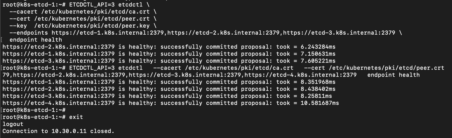
At this point, we have a running 4-node etcd cluster providing a highly available data store for the Kubernetes control plane.
Kubernetes API Load Balancer
To achieve a highly available Kubernetes API server, we will set up a load balancer in front of the control plane nodes. We’ll use two nodes (lb-1 and lb-2) running HAProxy for load balancing and Keepalived for failover (VRRP). These will maintain a virtual IP (VIP) that the Kubernetes API clients will use. In our setup, we will use the VIP 10.30.0.20 for the Kubernetes API server.
Both lb-1 and lb-2 will run HAProxy (with identical configurations) and Keepalived (with complementary configurations for MASTER/BACKUP).
First, install HAProxy and Keepalived on both load balancer nodes:
sudo apt update
sudo apt install -y haproxy keepalived
HAProxy Configuration
We will configure HAProxy to handle three forwarding scenarios:
- Internal API Server Load Balancing: Listen on the internal VIP (
10.30.0.20:6443) for Kubernetes API traffic within the cluster/network. - External API Server Load Balancing: Listen on an external IP (public-facing) on port
6443for Kubernetes API traffic from outside. - External Ingress Load Balancing: Listen on external IP(s) on ports
80and443to forward to the cluster’s Ingress controller service.
On each LB node, edit /etc/haproxy/haproxy.cfg (you can start from the default and modify accordingly). Use the configuration below as a guide:
global
    log /dev/log local0
    log /dev/log local1 notice
    chroot /var/lib/haproxy
    maxconn 100000
    user haproxy
    group haproxy
    daemon

defaults
    log     global
    mode    tcp
    option  tcplog
    option  dontlognull
    option  tcpka
    timeout connect 5s
    timeout client  300s
    timeout server  300s
    timeout tunnel  1h
    retries 3

# Use our internal DNS servers for service discovery (SRV records)
resolvers cluster_dns
    nameserver dns1 10.30.0.51:53
    nameserver dns2 10.30.0.52:53
    accepted_payload_size 8192
    hold valid 10s

# ---------- Internal Kube-API VIP ----------
frontend k8s_apiserver_internal_fe
    bind 10.30.0.20:6443
    default_backend k8s_apiserver_be

# ---------- External Kube-API (Public) ----------
frontend k8s_apiserver_public_fe
    bind <external-ip>:6443
    default_backend k8s_apiserver_be

# Backend for Kubernetes API servers
backend k8s_apiserver_be
    balance leastconn
    option tcp-check
    # Use DNS SRV records to discover API server endpoints (masters)
    server-template apiserver 4 _apiserver._tcp.k8s.internal resolvers cluster_dns resolve-prefer ipv4 check

# ---------- External Ingress (HTTP) ----------
frontend ingress_http_fe
    bind <external-ip>:80
    default_backend ingress_http_be

backend ingress_http_be
    mode tcp
    balance leastconn
    option tcp-check
    server lbvip 10.30.0.100:80 check

# ---------- External Ingress (HTTPS) ----------
frontend ingress_https_fe
    bind <external-ip>:443
    default_backend ingress_https_be

backend ingress_https_be
    mode tcp
    balance leastconn
    option tcp-check
    server lbvip 10.30.0.100:443 check

# Statistics (optional)
listen stats
    bind <internal-ip>:8404
    mode http
    stats enable
    stats uri /stats
    stats refresh 5s
Notes on the above configuration:
- We defined a resolvers
cluster_dnssection to tell HAProxy to use our CoreDNS servers for resolving DNS records. We will use this for service discovery of the API servers via SRV records. - The
k8s_apiserver_internal_feandk8s_apiserver_public_fefrontends both point to the samek8s_apiserver_bebackend. The internal one listens on the internal VIP (10.30.0.20) and the external one listens on some<external-ip>(replace this with the actual public or external IP of your LB nodes). - The server-template in the backend uses the DNS SRV records
_apiserver._tcp.k8s.internalto automatically populate server entries for the API servers. We specify 4 as the expected number of endpoints (since we have 4 masters). This way, as long as our DNS is up to date, we don’t need to hardcode the IPs of master nodes in the HAProxy config. - Two frontends (
ingress_http_feandingress_https_fe) listen on ports80and443of the external IP. They forward traffic to an internal service VIP10.30.0.100on ports80and443respectively. We plan to assign the Ingress Controller Service a ClusterIP or LoadBalancer IP of10.30.0.100, and HAProxy will pass external traffic to that service VIP (which in turn will route to the Ingress Controller pods). You could also have HAProxy directly point to the Ingress controller pods or nodeports, but using a service VIP is convenient. - Replace
<external-ip>with the actual external/public IP for each LB node, and<internal-ip>with the node’s internal IP (in our case, lb-1’s internal IP is10.30.0.41, lb-2’s is10.30.0.42). The stats UI bound to <internal-ip>:8404 is optional. - The
net.ipv4.ip_nonlocal_bind=1sysctl is important on the LBs so that HAProxy can bind to the VIP (10.30.0.20) even if it’s not currently on that node (Keepalived will manage moving it).
After editing the config, enable the kernel setting for non-local bind and restart HAProxy:
echo 'net.ipv4.ip_nonlocal_bind=1' | sudo tee /etc/sysctl.d/99-haproxy.conf
sudo sysctl --system
sudo systemctl enable --now haproxy
sudo systemctl restart haproxy
Keepalived Configuration
Now configure Keepalived on the two LB nodes to manage the failover of the VIP (10.30.0.20). We’ll use VRRP in unicast mode (since we don’t assume multicast is available).
On LB-1 (the primary), create /etc/keepalived/keepalived.conf with the following content:
vrrp_script chk_haproxy {
    script "pidof haproxy"
    interval 2
    weight -10
}

vrrp_instance VI_K8S_API {
    state MASTER
    interface eth0
    virtual_router_id 51
    priority 120
    advert_int 1

    # Define the peer for unicast
    unicast_src_ip 10.30.0.41        # LB-1's own IP
    unicast_peer {
        10.30.0.42                  # LB-2's IP
    }

    authentication {
        auth_type PASS
        auth_pass 7c7b6b9a          # password for VRRP (use any random string, must match on both)
    }

    virtual_ipaddress {
        10.30.0.20/24 dev eth0 label eth0:vip
    }

    track_script {
        chk_haproxy
    }

    notify_master "/usr/local/sbin/vip_notify.sh MASTER"
    notify_backup "/usr/local/sbin/vip_notify.sh BACKUP"
    notify_fault  "/usr/local/sbin/vip_notify.sh FAULT"
}
On LB-2, the config is similar but with state BACKUP and a lower priority:
vrrp_script chk_haproxy {
    script "pidof haproxy"
    interval 2
    weight -10
}

vrrp_instance VI_K8S_API {
    state BACKUP
    interface eth0
    virtual_router_id 51
    priority 110
    advert_int 1

    unicast_src_ip 10.30.0.42        # LB-2's own IP
    unicast_peer {
        10.30.0.41                  # LB-1's IP
    }

    authentication {
        auth_type PASS
        auth_pass 7c7b6b9a
    }

    virtual_ipaddress {
        10.30.0.20/24 dev eth0 label eth0:vip
    }

    track_script {
        chk_haproxy
    }

    notify_master "/usr/local/sbin/vip_notify.sh MASTER"
    notify_backup "/usr/local/sbin/vip_notify.sh BACKUP"
    notify_fault  "/usr/local/sbin/vip_notify.sh FAULT"
}
A few important points about this configuration:
- We use a vrrp_script called
chk_haproxyto monitor whether the HAProxy process is running. If HAProxy stops, the script will fail and reduce the priority by 10, which can trigger a failover. - We set
virtual_router_id 51(this can be any number 0-255, but must be the same on both nodes). - We use unicast VRRP (
unicast_src_ipandunicast_peer) with the two nodes’ IPs since multicast may not be enabled/allowed. - Both nodes share the same
auth_pass(a password for the VRRP messages). - We assign the virtual IP
10.30.0.20/24oneth0aseth0:vip. - We call a notification script on state changes (to log or perform gratuitous ARP).
Create the notify script /usr/local/sbin/vip_notify.sh on both LB nodes to handle transitions (this script will send a gratuitous ARP when becoming MASTER, to update network neighbors with the MAC of the new VIP holder):
#!/usr/bin/env bash
STATE="$1"
VIP="10.30.0.20"
IFACE="eth0"

case "$STATE" in
  MASTER)
    # Send 3 gratuitous ARPs for the VIP
    arping -c 3 -A "$VIP" -I "$IFACE" >/dev/null 2>&1 || true
    logger -t keepalived "Became MASTER for VIP $VIP"
    ;;
  BACKUP|FAULT)
    logger -t keepalived "State $STATE for VIP $VIP"
    ;;
esac
Make the script executable:
sudo chmod +x /usr/local/sbin/vip_notify.shNow start Keepalived on both nodes:
sudo systemctl enable --now keepalived
sudo systemctl restart keepalived
Keepalived will elect LB-1 as MASTER (higher priority) and LB-2 as BACKUP. The VIP 10.30.0.20 should now be visible on LB-1’s network interface (eth0:vip) and not on LB-2.
Testing the Load Balancers
- Service Status: Check that both HAProxy and Keepalived are running on both nodes without errors:
sudo systemctl status haproxy sudo systemctl status keepalived - VIP Assignment: On each LB, run ip a and ensure that
10.30.0.20is only present on the MASTER’s interface. If you stop keepalived on the master, the backup should take over the VIP within a second or two. - Connectivity: From any node on the network (or a client machine), test the API VIP:
This should report that the port is open (you can also usenc -zv 10.30.0.20 6443curl -k https://10.30.0.20:6443/healthzonce the API server is running, which we will set up next).
At this point, we have a highly available front-end (VIP + two HAProxy instances) ready to accept traffic for the Kubernetes API server (port 6443) and Ingress (ports 80/443) and distribute it appropriately.
Kubernetes Control Plane Setup
With etcd and the load balancer in place, we can proceed to set up the Kubernetes control plane nodes and then the worker nodes.
We will start by initializing the first control plane (master) node, then join the remaining control planes to the cluster, and finally join all worker nodes.
Copy etcd Certificates to Control Planes
Because we are using an external etcd cluster, the Kubernetes API server on each control plane node will need the etcd CA certificate and the API server etcd client certificate/key to authenticate with etcd.
Copy the following files from the etcd node where they were generated (e.g., etcd-1) to each control plane node (e.g., master-1), placing them under /etc/kubernetes/pki/etcd/ on the master:
ca.crt(the etcd CA certificate) ->/etc/kubernetes/pki/etcd/ca.crtapiserver-etcd-client.crt->/etc/kubernetes/pki/apiserver-etcd-client.crtapiserver-etcd-client.key->/etc/kubernetes/pki/apiserver-etcd-client.key
Do this for master-1 before initialization, and ensure the same files are present on master-2, master-3, master-4 before you join them (you can copy them to all masters now, or use kubeadm upload-certs feature to distribute, but copying manually is straightforward in this case).
Initialize the First Control Plane Node
On master-1, create a kubeadm configuration file (for cluster initialization) at /root/kubeadm-config.yaml with the following content:
apiVersion: kubeadm.k8s.io/v1beta4
kind: ClusterConfiguration
kubernetesVersion: stable
controlPlaneEndpoint: "api.k8s.internal:6443"
etcd:
  external:
    endpoints:
      - https://etcd-1.k8s.internal:2379
      - https://etcd-2.k8s.internal:2379
      - https://etcd-3.k8s.internal:2379
      - https://etcd-4.k8s.internal:2379
    caFile: /etc/kubernetes/pki/etcd/ca.crt
    certFile: /etc/kubernetes/pki/apiserver-etcd-client.crt
    keyFile: /etc/kubernetes/pki/apiserver-etcd-client.key
apiServer:
  certSANs:
    - api.k8s.internal
    - apiserver.k8s.internal
    - kubernetes.k8s.internal
    - api.k8s.mydomain.com       # (example external domain, if needed)
    - 10.30.0.20                 # API VIP
    - kubernetes
    - kubernetes.default
    - kubernetes.default.svc
    - kubernetes.default.svc.cluster.local
networking:
  podSubnet: "10.244.0.0/16"
  serviceSubnet: "10.96.0.0/12"
A few things to note in this config:
controlPlaneEndpointis set toapi.k8s.internal:6443– this is the DNS name that resolves to our API VIP (10.30.0.20). kubeadm will configure the API server to advertise this as the endpoint for the control plane. It’s important this DNS name is resolvable (which is why we set up CoreDNS).- The
etcd.externalsection lists the etcd cluster endpoints and the certs to use for connecting. We point kubeadm to our etcd cluster’s TLS assets. apiServer.certSANsincludes the internal DNS names and VIP, and optionally any external name (hereapi.k8s.mydomain.comis an example if you have a public DNS name for your API) that the API server’s certificate should cover. We also include the default Kubernetes service DNS names.podSubnetandserviceSubnetare set to the ranges we plan to use for pods and services. We will use Flannel or Calico later with the pod subnet10.244.0.0/16in this example.
Now, initialize the Kubernetes control plane:
sudo kubeadm init --config kubeadm-config.yaml --upload-certsThis will take a short while to generate all certificates and start the control plane components (API server, controller manager, scheduler) on master-1. Once it completes, it should end with instructions and join commands. Save this output or copy the join commands for use later. It will look similar to:
Your Kubernetes control-plane has initialized successfully!

To start using your cluster, you need to run the following as a regular user:

  mkdir -p $HOME/.kube
  sudo cp -i /etc/kubernetes/admin.conf $HOME/.kube/config
  sudo chown $(id -u):$(id -g) $HOME/.kube/config

Alternatively, if you are the root user, you can run:
  export KUBECONFIG=/etc/kubernetes/admin.conf

... (Installing pod network add-on message) ...

You can now join any number of control-plane nodes by running the following command on each as root:

  kubeadm join api.k8s.internal:6443 --token <your-token> \
    --discovery-token-ca-cert-hash sha256:<hash> \
    --control-plane --certificate-key <certificate-key>

Then you can join any number of worker nodes by running the following on each as root:

  kubeadm join api.k8s.internal:6443 --token <your-token> \
    --discovery-token-ca-cert-hash sha256:<hash>
Follow the on-screen instructions to set up your kubeconfig (on master-1) so that you can use kubectl. For example, if you are root, you can do:
export KUBECONFIG=/etc/kubernetes/admin.confNow your kubectl command (on master-1) should interface with the new cluster.
Join Additional Control Plane Nodes
On master-2, master-3, and master-4, run the kubeadm join ... --control-plane command provided by the output of kubeadm init. It will look something like:
sudo kubeadm join api.k8s.internal:6443 --token <token> \
    --discovery-token-ca-cert-hash sha256:<hash> \
    --control-plane --certificate-key <certificate-key>
This will join each of those nodes as additional control plane nodes. They will retrieve the necessary cluster certificates (including the certs we uploaded with --upload-certs) and start the control plane components on each.
Important: Ensure that the etcd CA and client certs (ca.crt, apiserver-etcd-client.crt, apiserver-etcd-client.key) have been copied to each of these nodes (under /etc/kubernetes/pki/etcd) before running the join command. If not, the API server on those nodes might fail to start because it cannot connect to etcd. If you used --upload-certs, the apiserver-etcd-client.crt/key might be distributed automatically, but the etcd CA (ca.crt) may need to be present. Double-check and copy if necessary.
At this stage, you have a multi-master control plane. You can verify by running on master-1 (with kubectl configured):
kubectl get nodes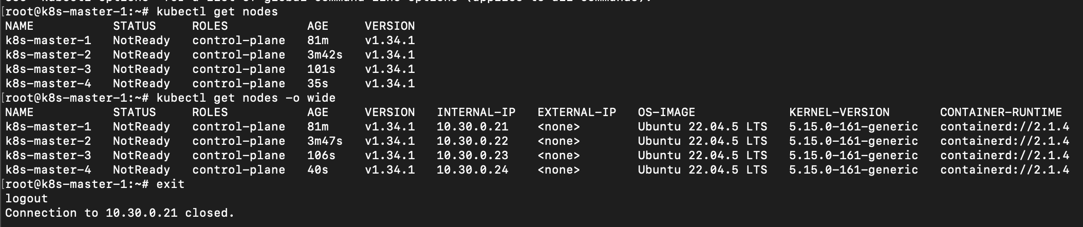
You should see master-1, master-2, master-3, master-4 listed (the control plane nodes might be in a NotReady state until we install the network plugin, which is expected).
Do not join worker nodes yet. We will first set up the CNI plugin (networking) so that when workers join, the cluster network is ready.
Install CNI (Calico) for Pod Networking
With the control plane up (but before adding workload nodes or running pods), we need to install a CNI plugin to handle pod networking. We will use Calico for this cluster, as it provides robust networking with support for network policies.
Calico can run in different dataplane modes (eBPF or standard Linux networking with IPTables). We will first install Calico in its standard mode (using IPTables), then later demonstrate switching to eBPF mode for potential performance benefits.
Make sure the podSubnet (10.244.0.0/16 in our case) we provided to kubeadm is what we configure in Calico.
Prerequisite: Ensure that on each node, the /etc/resolv.conf does not have any unexpected search domains and that resolv.conf is configured either via systemd-resolved as we did or points to a valid DNS. Having extra search domains can sometimes cause issues with the Calico DNS daemon or Kubernetes DNS.
Install Calico (Operator Deployment, IPTables Mode)
We will apply the Calico Operator manifests, which will install the Tigera operator and custom resource definitions (CRDs), then we’ll create the custom resource to configure Calico.
Apply the Calico operator and CRDs (use the latest version or v3.31 as in this example):
kubectl apply -f https://raw.githubusercontent.com/projectcalico/calico/v3.31.0/manifests/operator-crds.yaml
kubectl apply -f https://raw.githubusercontent.com/projectcalico/calico/v3.31.0/manifests/tigera-operator.yaml
Now, create a Calico Installation resource to configure the Calico networking. Save the following as calico-custom-resources.yaml:
apiVersion: operator.tigera.io/v1
kind: Installation
metadata:
  name: default
spec:
  calicoNetwork:
    bgp: Enabled
    linuxDataplane: Iptables
    # We start with standard IPTables dataplane; will switch to eBPF later if desired.
    ipPools:
      - blockSize: 26
        cidr: 10.244.0.0/16       # This must match the podSubnet given to kubeadm
        encapsulation: IPIP       # IP-in-IP encapsulation for cross-subnet traffic
        natOutgoing: Enabled
        nodeSelector: "all()"     # Use this pool on all nodes

---
apiVersion: operator.tigera.io/v1
kind: APIServer
metadata:
  name: default
spec: {}

---
# These enable Calico's flow logs API (Goldmane) and the web UI (Whisker) – optional
apiVersion: operator.tigera.io/v1
kind: Goldmane
metadata:
  name: default
spec: {}

---
apiVersion: operator.tigera.io/v1
kind: Whisker
metadata:
  name: default
spec: {}
Apply this manifest:
kubectl apply -f calico-custom-resources.yamlCalico’s operator will proceed to install the necessary components (calico-node DaemonSet, calico-kube-controllers, etc.). It may take a couple of minutes for all pods to be up and running. You can check the status with:
kubectl get pods -n calico-systemAll pods (calico-node on each node, calico-kube-controllers, tigera-operator, etc.) should eventually show as Running.
Note: We included the Calico Goldmane and Whisker resources, which correspond to an API for flow logs and a web UI for observability (these require additional setup like provisioning an ingress or NodePort to access the UI, and possibly storage for flow logs, but simply applying them doesn’t harm anything if not used).
Now that Calico is installed (in IPTables mode), the cluster network is ready. The control plane nodes should now be Ready (since the kube-proxy and CoreDNS pods can now operate across the network).
Configure Cluster DNS to Forward k8s.internal
Recall that earlier, we set up our node host’s systemd-resolved to handle k8s.internal. However, pods in the cluster will use the Kubernetes CoreDNS (running as a Deployment in the cluster) for DNS resolution. By default, pods’ DNS (CoreDNS) knows about cluster service names (cluster.local) and forwards other queries to the host’s resolvers (which, thanks to our earlier config, cover k8s.internal). However, in some cases, if the pods inherit a search domain or other settings, they might not resolve k8s.internal correctly.
To be safe, we will explicitly configure the Kubernetes CoreDNS to forward queries for k8s.internal to our external CoreDNS servers.
Edit the CoreDNS ConfigMap:
kubectl edit configmap/coredns -n kube-systemIn the Corefile, add a forwarding rule for the k8s.internal domain above the default forward rule. It should look like this:
.:53 {
    # ... existing config ...
    kubernetes cluster.local in-addr.arpa ip6.arpa { ... }

    prometheus :9153

    # Forward k8s.internal queries to our internal DNS servers
    forward k8s.internal 10.30.0.51 10.30.0.52 {
        max_concurrent 1000
    }

    # Forward all other queries to the upstream resolvers (from /etc/resolv.conf)
    forward . /etc/resolv.conf {
        max_concurrent 1000
    }

    cache 30 {
        # ... cache settings ...
    }
    loop
    reload
    loadbalance
}
This ensures that any DNS query from a pod for something like api.k8s.internal will be sent to 10.30.0.51/52, which are our CoreDNS servers on the host network.
Save the ConfigMap. Kubernetes will automatically rollout the changes to the CoreDNS pods (or restart them). You can monitor with kubectl get pods -n kube-system -l k8s-app=kube-dns -w to see them restart quickly.
Join Worker Nodes to the Cluster
Now that networking is in place, you can join your worker nodes to the cluster. Use the second join command that was given by kubeadm init (the one without the --control-plane flag). It looks like:
sudo kubeadm join api.k8s.internal:6443 --token <token> \
    --discovery-token-ca-cert-hash sha256:<hash>
Run this on each worker node (worker-1 through worker-8). After a short time, they should join the cluster.
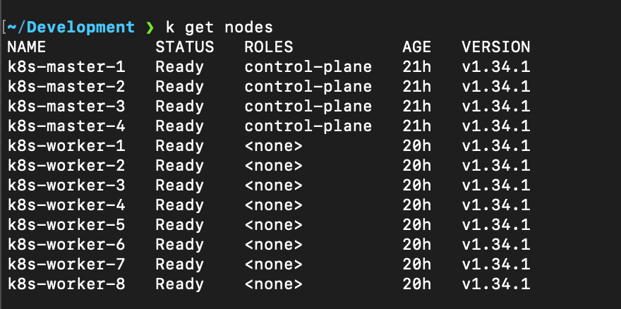
Verify on master-1 with:
kubectl get nodesAll workers should appear, initially in NotReady until Calico pods start on them. The Calico operator will automatically deploy calico-node DaemonSet pods on each new node, which should then report Ready.
Test Pod Network Connectivity
To ensure everything is working (DNS, networking, etc.), let’s run a simple test:
# Launch a temporary pod for testing
kubectl run -it --rm --image=ubuntu:22.04 test-pod -- bash
This will schedule a single Pod running Ubuntu. Once you’re inside the pod’s shell:
# Install tools inside the pod
apt update && apt install -y iputils-ping dnsutils

# Test DNS resolution within the pod
nslookup kubernetes.default.svc.cluster.local   # Kubernetes service DNS
nslookup api.k8s.internal                       # Our internal API DNS name
nslookup www.google.com                         # External DNS resolution

# Test connectivity to another pod or service if available.
# For example, deploy a second test pod and try to ping it by IP.
exit
Exit will terminate the pod (since we used --rm). If DNS lookups work (especially api.k8s.internal resolving to 10.30.0.20), and you can ping between pods (note: by default Calico allows all pod traffic, but if you installed network policies or default deny, adjust accordingly), then the networking is functioning correctly.
Verify Overall Cluster Status
Check that all system pods are running as expected:
kubectl get pods -AEnsure kube-system pods like CoreDNS, kube-proxy, calico-node, calico-kube-controllers, etc., are healthy. Also check Calico’s status resource:
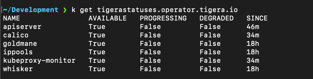
kubectl get tigerastatus -n calico-systemThere should be an object like calico or general that indicates components are healthy (Available). If anything is not available, describe that tigerastatus for clues.
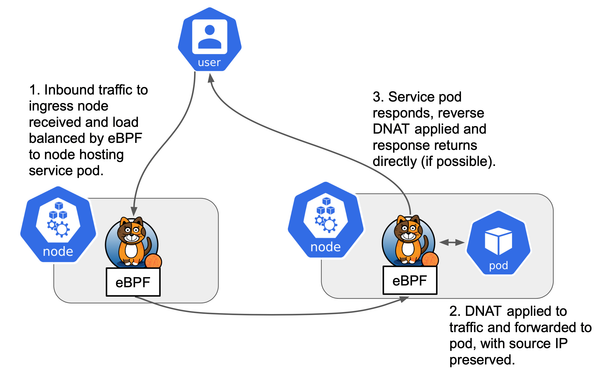
(Optional) Switching Calico to eBPF Mode
Calico’s eBPF dataplane can provide performance and feature benefits (like bypassing kube-proxy, better network isolation, etc.) at the cost of higher kernel requirements and some feature differences. If you decide to use eBPF mode, consult Calico’s documentation on eBPF use cases to ensure it fits your needs.

To switch to eBPF mode, we will update the Calico Installation resource and then apply it, which will rolling-update the calico components:
Edit calico-custom-resources.yaml (or patch the Installation) to set linuxDataplane: BPF and add the necessary options:
apiVersion: operator.tigera.io/v1
kind: Installation
metadata:
  name: default
spec:
  calicoNetwork:
    bgp: Enabled
    linuxDataplane: BPF
    bpfNetworkBootstrap: Enabled    # Enable BPF mode bootstrap (programming BPF before pods start)
    kubeProxyManagement: Enabled    # Let Calico replace kube-proxy functionality
    ipPools:
      - blockSize: 26
        cidr: 10.244.0.0/16
        encapsulation: None         # No overlay (BPF mode uses native routing)
        natOutgoing: Enabled
        nodeSelector: "all()"
Important changes:
- We set
linuxDataplane: BPF. bpfNetworkBootstrap: Enabledallows Calico to preconfigure BPF for workloads.kubeProxyManagement: Enabledlets Calico’s eBPF replace kube-proxy (for service handling via XDP/BPF).encapsulationis set toNonebecause in eBPF mode, IPIP is not needed (unless your network requires an overlay, but typically eBPF can do native routing and handle cross-subnet via encapsulation-less means or direct routing).
Apply the updated resource:
kubectl apply -f calico-custom-resources.yamlThis will trigger the Calico operator to roll out changes. It may reboot Calico pods. It will also remove kube-proxy if kubeProxyManagement is enabled (since Calico will handle service routing).
Monitor the status of Calico:
kubectl get tigerastatusYou should see the status progressing and eventually all components should be Available. For example, a calico status resource should indicate BPF mode in use. You can also confirm that the kube-proxy pods are gone and the calico-node pods have restarted in BPF mode.
After switching to BPF, run the connectivity tests again (DNS, cross-pod traffic, service access) to ensure everything works in the new mode.
Next Steps
Congratulations! You have deployed a highly available Kubernetes cluster with multiple etcd nodes and control planes, an external CoreDNS for cluster DNS, and an external HAProxy/Keepalived load balancer for the API server and ingress.
Possible next steps to consider for a production-ready environment:
- Deploy an Ingress Controller: Install an ingress controller (e.g., NGINX Ingress Controller, Traefik, etc.) to manage external HTTP/HTTPS access to your services. In our setup, you would assign it the
10.30.0.100virtual IP (as configured in HAProxy) or adjust accordingly. - Monitoring and Logging: Set up monitoring (Prometheus & Grafana) and logging (EFK/ELK stack or other solutions) to collect metrics and logs from your cluster. Monitor etcd, API server, and CoreDNS closely since they are critical components.
- Security Policies: Implement Network Policies (Calico supports them out-of-the-box) to restrict traffic between pods as needed. Also consider Pod Security Standards (or PodSecurityPolicy in older clusters) and RBAC policies to enforce least privilege for users and service accounts.
- Backup and DR: Configure backups for etcd (since it contains all cluster state). You can use etcdctl snapshot or tools like Velero for higher-level backups of cluster state and resources.
- Deploy Applications: With the infrastructure in place, you can start deploying your workloads to the cluster. Use taints/tolerations or node selectors if you want to isolate certain workloads to specific nodes (e.g., run system or critical workloads on specific nodes, etcd nodes should be tainted NoSchedule for normal pods, which kubeadm does by default when stacking etcd on control planes — in our case etcd nodes aren’t part of the Kubernetes cluster at all, so no need here).
With this setup, you should have a robust environment capable of tolerating failures at multiple levels (etcd node failure, master node failure, load balancer node failure) without causing cluster downtime. Make sure to test various failure scenarios (powering off an etcd node, restarting a master, failing over the VIP, etc.) to be confident in the cluster’s resilience.
Happy clustering!