Infrastructure Design for Self-Hosted Kubernetes Clusters
This article examines how to build a self-hosted Kubernetes cluster on bare-metal infrastructure, focusing on networks, high availability, DNS, and storage. It targets academic infrastructure engineers managing clusters under 50 nodes, contrasting with managed cloud solutions.


Self-hosting Kubernetes on bare-metal or virtualized (e.g. Proxmox VE) brings full control and customization compared to managed cloud services. On-prem clusters let organizations tailor hardware, networking, and storage to specific needs (e.g. GPUs, FPGAs, existing systems). They also keep data under direct control, which eases compliance with data residency and sovereignty requirements. However, these clusters incur significant capital expenditure (CAPEX) and recurring costs for power, space, and maintenance, whereas public cloud replaces most of that with pay-as-you-go operational expenditure (OPEX). Notably, high-volume network traffic can make bare-metal clusters more cost-effective: one study found that cloud egress charges make on-premises hosting “more economical” for network-intensive workloads. In contrast, managed Kubernetes (EKS, AKS, GKE, etc.) offloads control‐plane maintenance, patching, and upgrades to the provider, simplifying operations for small teams.
Key differentiators include latency and data governance. A local on-prem cluster typically offers lower, more deterministic network latency for intra-cluster and local client traffic than a multi‐AZ cloud cluster. On the other hand, cloud providers offer high-availability across geographic zones and mature SLAs (e.g. 99.95% uptime for control plane) at the cost of cross‑region latency and reliance on provider networks. Self-hosted clusters give complete control over where data resides, helping meet strict jurisdictional or privacy regulations. In contrast, public cloud imposes data localization rules (e.g. GDPR) and puts data “in the hands of the provider”, which may be unacceptable in some enterprises or research environments.

In summary, on-prem Kubernetes suits cases demanding tight integration with local systems, custom hardware, or strict data governance. Cloud-managed Kubernetes excels in ease of use, global scale, and reducing operational burden. The remainder of this article assumes a production-grade on-prem deployment (≤50 nodes) and examines design decisions in networking, storage, HA, DNS, and failover strategies. We highlight best practices and trade-offs for academic or enterprise infrastructure teams.
Self-Hosted vs. Managed Clusters
Cost and Infrastructure Trade-Offs
On-premises clusters require significant upfront investment in servers, networking and facilities (power, cooling, racks). Their total cost of ownership includes CAPEX depreciation and fixed costs that do not apply in cloud environments. By contrast, public-cloud Kubernetes turns infrastructure into variable OPEX (per-node and per-hour pricing). However, analyses show cloud costs can escalate with heavy network usage: since cloud providers often charge egress network fees, on-premises hosting yields “significant network cost savings” for chatty or bandwidth-intensive applications.
In a managed cloud service, you pay a premium for convenience (control-plane SLA, automated upgrades, multi-AZ support). But you forgo flexibility: infrastructure choices (instance types, networking modes, available regions) are determined by the provider. For example, a managed K8s might restrict certain CNI plugins or GPU types. In on-prem setups, you choose the exact hardware and networking, at the price of needing skilled operations staff to manage it.
Ongoing Operational Overhead
Self-hosted clusters demand a dedicated team of Kubernetes experts to maintain etcd, control-plane backups, upgrades, and cluster scaling. Even routine tasks like patching require manual planning. Managed services significantly reduce this staffing burden: the provider handles etcd scaling, control-plane redundancy, and patch distribution. This difference is often cited as a key reason enterprises opt for cloud K8s when expertise or headcount is limited.
Latency and Performance
Latency between nodes and services is critical for distributed applications. In an on-prem physical network (especially within the same rack or data center), round-trip latency can be <1 ms. In contrast, even intra-AZ cloud traffic may incur 2–3 ms, and cross-AZ or cross-region traffic can be tens of milliseconds. For low-latency or high-throughput workloads (e.g. HPC, high-frequency trading), on-prem bare-metal often outperforms cloud instances. However, note that enterprise networks may still have bottlenecks; careful topology (e.g. spine-leaf switches with redundant links) is needed to avoid oversubscription. The design should account for east-west pod traffic and north-south ingress, ensuring adequate bandwidth and QoS.
Data Governance and Security
On-prem clusters keep data fully under your control, which simplifies compliance with data sovereignty and privacy laws. For example, sensitive research data in academia or regulated patient data must often remain within certain jurisdictions or avoid third-party access. Public clouds offer region selection, but data may still traverse global networks (e.g. for replication or multi-zone services) potentially violating policies. In contrast, private infrastructure can be locked down to known network boundaries. Of course, in-house security becomes critical: physical security, on-site firewalls, and strict access policies must be enforced.
Cloud providers invest heavily in infrastructure reliability (multiple zones, automated backups, hardened hardware), often achieving “five nines” SLAs on managed control planes. On-prem deployments must architect their own reliability through redundancy of components (e.g. dual power supplies, RAID disks, NIC bonding, multiple masters), which increases complexity. It is vital to design for single points of failure: any single-host component (like a single master API endpoint without failover) can threaten availability.
Network Architecture
Physical Topology and Segmentation
A production bare-metal K8s cluster typically uses redundant network fabrics. Common practice is a leaf-spine or two-tier switch design with dual-homed servers (each server connected to two Top-of-Rack switches via bonded NICs for LACP). Critical traffic (e.g. storage, cluster control, container overlay) is separated into VLANs or even physically separate networks to avoid interference. For instance, one VLAN (or dedicated NIC) might carry Ceph/storage traffic, another carries Kubernetes pod and service traffic, and a management VLAN handles cluster provisioning. This ensures heavy storage I/O (Ceph replication) cannot saturate the K8s data plane, improving performance and reliability.
VLAN segmentation is key. If using ARP/NDP-based IP failover (VRRP) or MetalLB ARP-mode for LoadBalancer services, all relevant servers must share the same L2 broadcast domain. As Mirantis notes, an ARP-mode external LB IP “must consist of a single VLAN stretched” across racks. In contrast, a BGP-based design (e.g. MetalLB BGP mode or router-based anycast) allows separate L3 networks per rack, improving isolation.
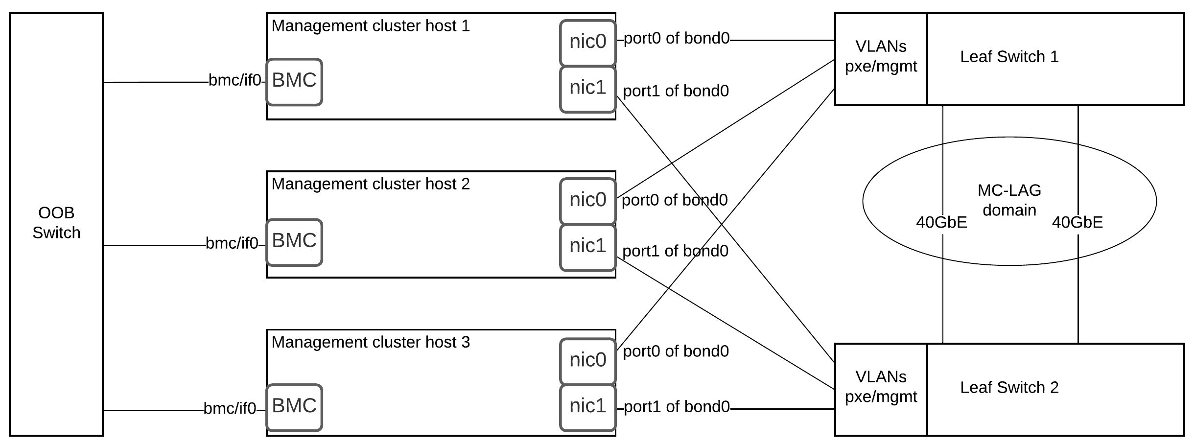
Figure: Example Proxmox VE network bridge configuration, illustrating VLAN tagging. Each physical node has Linux bridges (e.g. vmbr1, vmbr2) tied to bonded interfaces (bond0), with VLAN tags (e.g. 2000 for Ceph, 2001 for Kubernetes) on the bond. In production bare-metal clusters, such bonding and VLANs are used to provide both throughput (via link aggregation) and traffic isolation. For example, Ceph replication traffic (very high throughput) would traverse a separate VLAN from pod-to-pod traffic, preventing noisy neighbors.
Dual-Stack (IPv4/IPv6) Support
Modern Kubernetes supports IPv4/IPv6 dual-stack networking out-of-the-box. This allows pods and services to have both IPv4 and IPv6 addresses simultaneously. In an on-prem context, using IPv6 can greatly simplify addressing (vast CIDR space) and potentially reduce NAT complexity. However, the physical network and all CNIs must support IPv6 routing. For smaller clusters (<50 nodes), many organizations still deploy IPv4-only for simplicity, unless there is a clear future need for IPv6 connectivity. If dual-stack is chosen, ensure proper DNS and routing for both families.

Virtual IPs and Load Balancing (VRRP vs External LB)
High-availability of the Kubernetes API requires a stable endpoint (VIP) that is not tied to a single node. Two common patterns are:
- Keepalived/VRRP + Software LB: Run Keepalived on control-plane nodes to float a virtual IP (VRRP) between them, combined with HAProxy or Nginx for load balancing API requests to local kube-apiservers. If the active node fails, VRRP moves the VIP to another master. For example, the VRRP VIP 10.30.12.100 might point to whichever master is currently
MASTER. HAProxy on each node listens on that VIP and proxies to the local API. This stacked approach (HAProxy on each master) is simpler to build if no external LB is available. - External Hardware/Virtual LB: Use a dedicated load balancer appliance (or virtual machine) with a floating cluster IP. This can be a physical F5, Cisco, or even a virtual F5/VyOS. The LB forwards to all healthy API servers. This separates control-plane responsibilities from the cluster nodes and can provide advanced features (SSL termination, health probes, etc.). The downside is single-vendor dependency and cost.
In either case, at least three control-plane nodes (with etcd quorum) are recommended for true HA. Kubernetes docs state: “You should run a minimum of three stacked control plane nodes for an HA cluster.”. Two nodes can tolerate one failure (if using asymmetric quorum) but are not recommended.
Network Segmentation and Bonding
At the NIC level, it is best practice to bond multiple physical interfaces for redundancy and throughput. For instance, two 10 Gbps NICs in LACP bond carry a VLAN trunk with multiple tagged networks (management, storage, pod overlay). Each bridge (vmbrX in Proxmox) can map a VLAN to a Linux bridge, isolating VM traffic. In Kubernetes, the network fabric (underlay) supports the container overlay (Flannel, Calico, etc.). It’s wise to dedicate one bonded pair (or NIC) per leaf switch to each server, minimizing failover domains.
Network devices (switches) should also be configured for HA: spanning tree or MLAG should allow for redundant links without loops. Link health monitoring (e.g. BFD if using BGP) and consistent MTU settings (especially if using VXLAN/overlay networks) are essential.
L2 vs L3 Load Balancing (MetalLB, Anycast)
For exposing services (Kubernetes Service.Type=LoadBalancer) in bare-metal, tools like MetalLB are used. MetalLB can operate in:
- ARP mode (L2): Speakers announce service IPs via ARP on a common VLAN, similar to VRRP. This requires one L2 domain per service IP.
- BGP mode (L3): Speakers peer with routers using BGP; routers then route the service IP to a specific node. This allows multi-subnet usage and faster convergence.
L2 (ARP) mode is simpler to set up, but it confines you to one broadcast domain per shared IP. L3 (BGP) mode is more complex (requires BGP configuration on top-of-rack devices) but scales to larger topologies without VLAN stretching. In mission-critical designs, BGP is preferred for cross-rack HA without relying on broadcast.

Storage Architecture
Distributed Storage (Ceph CSI)
For durable storage, many on-prem clusters use a distributed system like Ceph. The Rook operator makes deploying Ceph on Kubernetes manageable: “Rook orchestrates the Ceph storage solution… Rook ensures that Ceph will run well on Kubernetes”. Ceph provides block (RBD), file (CephFS), and object (RGW) storage, all via CSI. A typical design runs Ceph OSDs on each node (using local disks), with monitors on control-plane or dedicated nodes. Ceph traffic should be on its own VLAN or switch; heavy I/O for replication or recovery can saturate links if mixed with regular pod traffic.

Ceph clusters themselves require odd number of monitors (usually 3 or 5) for quorum. For a <50‑node cluster, having 3 Ceph mons on 3 different hosts is common. If using virtual machines (e.g. Proxmox VMs) for monitors/OSDs, ensure that the hypervisor has pass-through or LVM devices for performance. SSDs or NVMe drives are often dedicated to OSDs for speed.
Local SSD / Ephemeral Storage
Local NVMe or SSDs on each node provide ephemeral storage (via emptyDir or local PVs) that is extremely fast. Local storage is suitable for caches, scratch space, or any temporary data. As Portworx notes, “Local ephemeral storage, such as node-local SSDs, typically provides significantly faster I/O than network-attached persistent storage due to reduced network overhead.” For example, a Redis cache or in-node database can benefit from local NVMe for high throughput. However, since it is node-specific, pods using local storage must tolerate node loss (no automatic data replication unless managed by StatefulSets with local PV policies).
If persistence is needed (data must survive pod restarts), use networked volumes (Ceph, NFS, iSCSI) or replicated PVCs. One hybrid approach is using CSI local persistent volumes: Kubernetes can treat a particular host disk as a PV, but it will only schedule the PVC on that host (using node affinity). This gives near-local performance for stateful apps.
Container Storage Interface (CSI)
Kubernetes uses CSI drivers to provision volumes on different backends. In bare-metal setups, common CSI drivers include:
- Ceph CSI: for dynamic Ceph volumes.
- Local Path Provisioner or Local Volume: for claiming entire local disks (not shared).
- NFS or GlusterFS: if a simple file-server is acceptable (less common in large scale).
Ensure CSI controllers (provisioners) and node plugins run on all relevant nodes (tolerations may be needed). Keep storage traffic isolated: e.g., mount Ceph OSD backend disks via a separate network (bonded NICs on VLAN 2000) to avoid interfering with pod network.
Control Plane High Availability
API Server Failover (HAProxy + Keepalived)
A typical HA design (without external LB) is to install Keepalived on each master. Keepalived implements VRRP to share a virtual IP (VIP) among masters. For example, masters A, B, C run Keepalived, with priorities (A highest, B next, etc.). The VIP floats to the current master. HAProxy runs on each master and listens on the VIP, balancing to the local kube-apiserver instance. If the master holding the VIP crashes, Keepalived moves the VIP to the next available master, and HAProxy on that node takes over serving the API.
This stacked approach (HAProxy+Keepalived on each master) is widely documented. Its advantages are simplicity and no need for extra hardware. Its drawbacks include more management overhead (configure Keepalived/HAProxy on every master). Another design is unstacked: have two dedicated LB VMs (or appliances) with VRRP between them, so that masters see an external VIP. The workload perspective is similar: a floating IP in front of all apiservers.
External Load Balancer
If budget allows, one can use a proper load balancer. For example, a pair of F5 LTM devices can be configured with a VIP for the Kubernetes API. These devices perform health checks on /healthz of each kube-apiserver, and route traffic accordingly. They also often support TLS offload or full proxy. Another option is using cloud-based LB even in on-prem (e.g. an AWS Classic LB via Direct Connect) though uncommon. External LBs introduce another vendor component, but can simplify certain operations (certificate handling, high throughput).
Etcd Clustering
Kubernetes’ data store etcd itself must be highly available. In a stacked control plane, each master runs an etcd member (Raft). Losing one member still keeps quorum if you have ≥3 members. For more resilience, some designs use external etcd: run 3 (or 5) etcd nodes separate from the API servers. External etcd decouples failures (you could lose a control-plane node without losing an etcd node) but doubles the number of hosts. In a cluster <50 nodes, most deployments use the simpler stacked approach with 3 master nodes total.
DNS is also critical: the cluster’s CoreDNS pods should be run with a PodDisruptionBudget and redundant replicas. If CoreDNS goes down, service discovery breaks. However, CoreDNS itself uses the Kubernetes API, so one could argue API HA is higher priority.
DNS Strategy
CoreDNS (In-Cluster DNS)
By default, Kubernetes uses CoreDNS (or kube-dns) for service discovery inside the cluster. CoreDNS runs as a Deployment in the kube-system namespace, typically with multiple replicas (often 2 or 3) tied to different nodes. It resolves <service>.<namespace>.svc.cluster.local names to internal cluster IPs. For production, ensure CoreDNS has enough CPU/memory (DNS lookups can be heavy) and that its pods are spread across nodes.
CoreDNS should have a dedicated service IP (default 10.96.0.10) and is usually fronted by kube-proxy. External clients inside the data center typically do not use CoreDNS directly; it’s only for in-cluster name resolution.
External DNS (Out-of-Band)
For name resolution from outside the cluster (e.g. other VMs, user PCs, or cloud networks), you may run an external DNS server. This could be a VM or hardware (BIND, Windows DNS, Infoblox, etc.) that knows about your cluster’s domain. Commonly, one creates A records (or wildcard records) pointing to the cluster IP (e.g. api.cluster.local -> 10.30.12.100) and any LoadBalancer service IPs. This “split-horizon” approach means internal clients use CoreDNS (for k8s service names), while external queries go to the enterprise DNS, which may forward unknown queries to CoreDNS via forwarding zones if needed.
Some setups integrate ExternalDNS (a Kubernetes operator) with corporate DNS, automatically updating records for Kubernetes services. This ensures applications exposed via Service=LoadBalancer get DNS names.
DNS Best Practices
- Use a short cluster domain (default
cluster.local). Avoid too deep labels. - Configure stub domains or forwarders: e.g. cluster nodes or external clients can forward
*.cluster.localqueries to CoreDNS. - Monitor DNS latency and cache (
stubDomainsinkubelet). High latency in DNS can slow down service calls. - Keep CoreDNS logs (and metrics) monitored via Prometheus for unexpected errors.
Failover and High-Availability Best Practices
Physical Redundancy
- NIC Bonding/LACP: Always bond NICs into at least 2-link aggregates, across different switches if possible, so a single cable or switch doesn’t kill a node’s connectivity.
- Dual Power Supplies: Rack servers and switches should use dual PDUs if available.
- Multiple Fans/PSUs: Use redundant cooling/PSU options.
- RAID and Multiple Disks: Use RAID1 or RAID10 for OS disks. For data disks (Ceph OSDs), having multiple disks per node allows continued operation if one disk fails.
Networking Failover (VRRP, BGP, etc.)
As noted, use VRRP (Keepalived) to fail over VIPs for control plane, and BGP (or MetalLB ARP) for service IPs. Also consider dynamic routing: in advanced designs, network switches run a routing protocol (e.g. OSPF/BGP) so that if a leaf switch dies, routers know alternate paths. While complex, this can automate failover.
Kubernetes-Level Resilience
- PodDisruptionBudgets: Prevent all replicas of an app from being down simultaneously during upgrades.
- Anti-Affinity: Place critical pods (e.g. long-running stateful workloads, CoreDNS, monitoring stack) on separate nodes to avoid correlated failure.
- Multi-Node etcd: As discussed, use 3+ masters so etcd quorum survives a node loss.
- Multi-Node Control Plane: Kubeadm’s default stacked etcd topology does not tolerate 2 simultaneous failures if using 3 nodes, so plan accordingly. For extreme cases, 5 masters with quorum 3 can survive 2 failures.
L2 vs L3 Considerations
As noted in the Mirantis guidance, an L2 “stretched VLAN” is required if using ARP for VIPs. If the hardware supports it, consider L3-based anycast for Kubernetes services (some clusters even assign the same IP on all nodes and rely on routing). L3 (BGP) is preferred for clusters spanning multiple racks or sites: it eliminates the single-broadcast-domain limitation and can reduce ARP/NDP traffic.
Backups and Disaster Recovery
Even with HA, absolute failures can happen. Maintain regular etcd backups (Kubernetes e.g. etcdctl snapshot save) stored off-cluster. Test restores periodically. Similarly, back up persistent volume data (for example, use Ceph’s RBD snapshots or replication to another site) especially if needed for compliance.
Example Deployment Layout
Figure: Example VM distribution across three physical Proxmox nodes for a HA Kubernetes cluster. In this sample design, three physical hosts (PVE-1, PVE-2, PVE-3) each run one master+etcd VM (APISVR1, APISVR2, APISVR3) and optionally a worker node VM. The table illustrates allocating CPU, RAM, and storage per VM. Separate additional hosts (PVE-4,5,6…) run only worker VMs to isolate application workloads. This separation ensures each etcd instance is on a different host, preserving quorum if one host fails. In practice, each Proxmox node would also configure Linux bridges and VLANs as in Figure 1, bonding NICs for throughput and segmenting network traffic.
In this scenario, the control-plane uses Keepalived to manage the API VIP among the three APISVR VMs, and HAProxy on each VM balances requests to the local kube-apiserver. MetalLB in BGP mode could provide service IPs across all workers on the management network. Ceph OSDs run on the same hosts (using dedicated disks) and connect via a separate VLAN (e.g. vmbr1:bond0.2000) not shown here.
Each application namespace has its own ResourceQuota for CPU, RAM, and storage. For example, user “Alice” might get 8 GiB RAM and 4 vCPU across her pods, while “Analytics” gets larger quotas on SSD-backed volumes. This isolation maps back to the underlying VM/host resources.
Conclusion
Designing a self-hosted Kubernetes cluster requires careful planning of hardware, networking, and services to achieve production-grade HA and performance. The choice between on-prem and cloud managed ultimately balances control vs convenience. On-prem offers lower latency, potentially lower network costs, and stronger data governance, at the expense of higher operational overhead and complexity. By following best practices—network VLAN segmentation, dual-master VRRP, bonded interfaces, distributed storage with Ceph, and redundant control planes—organizations can build robust clusters tailored to their requirements.